5.4 KiB
SomfyController
A controller for Somfy RTS blinds
Most of my home is automated and one of the more annoying aspects are three very expensive roller shades that still don't have any type of automation attached to them. So I went searching for libraries that could automate my shades. Not only automate them but interact with them but manage their position while still allowing me to use the Telis remotes.
The research led me to several projects that looked like they would do what I want. Most of them however, could send commands using a CC1101 radio attached to an ESP32 but I really wanted to be able to capture information from any external remotes as well. In the end I did not find what I wanted so this repository was born.
This software uses a couple of hardware components. These include an ESP32 module and a CC1101 Transceiver module. The CC1101 is connected via SPI to the ESP32 and controlled using SmartRC-CC1101-Driver library.
Getting Started
Originally I bought a spring type transceiver module and could not figure out why it would not consistently receive commands from my remotes. I then went about purchasing several other transceiver modules. This led me to the conclusion that the timing algorithm I created to read the radio signal was not quite ready and any of the CC1101 transceivers work. All of them had a range over 300 feet and through a couple of walls. I finally just stopped walking.
Your first step is to connect your transceiver to your ESP32. I did this with the use of some dupont connections for now but will be coming up with a cleaner setup and project enclosure. Next you will want to install the firmware on your ESP32 and configure the radio to match your hardware connections.
Required Hardware
- 1 - ESP32 Module
- 1 - CC1101 Transceiver Module
- 8 - Dupont female/female connectors
Assembling the Hardware
You will need an ESP32 module. I used an ESP32S-WROOM-32 deevelopment board for my project. The included binary is compiled using this board. You will also need a CC1101 transceiver module. Like I explained earlier I bought several of these and they all work great. I have the blue ones with 10 pins, green ones with 8 pins, and even blue ones with 8 pins. The 10 pin versions simply have the VCC and ground pins duplicated.
The hardest part of the inital connection is determining which pins are which on the transceiver. Sadly the first module (green 8-pin) I bought only had the pins labeled with a number. As it turns out the mapping goes like this if you bought one of these boards.
| Pin | Description | ESP Pin |
|---|---|---|
| 1 | GND | GND |
| 2 | VCC | 3v3 |
| 3 | GDO0 - This is the RX Pin | GPIO 13 |
| 4 | CSN | GPIO 5 |
| 5 | SCK | GPIO 18 |
| 6 | MOSI | GPIO 23 |
| 7 | MISO | GPIO 19 |
| 8 | GDO2 - This is the TX pin | GPIO 12 |
This is how I mapped mine using the V-SPI interface of the ESP32 and two innocuous pins for RX/TX. Initially I used the onboard LED pin for RX to see when data was being sent but I think that was causing interference. If you just want this to work use the pin mapping above. The other boards are much better labeled so match up the descriptions to the pin header and you will be golden.
Installing the Software
I developed this using the painfully awful Arduino IDE v1.8. I originally installed v2.0 then found out you cannot upload the file data to it so use v1.8 and save yourself several hours of searching through forums for functions that are not supported even several years after its release. If you are using VS Code then you are on your own. The good news is that you only need this during the initial install.
First compile and upload the firmware to the ESP32. Then upload the data using the Sketch Data upload tool. You will be happy to know that once the initial install is done you don't have to go through all these hoops to update the firmware or the LittleFS file system if you are using an ESP32S-WROOM-32 module. I created a utility that is part of the software. You can install the firmware and the applicaton files remotely.
If you are unfamiliar with uploading sketches this is an opportunity to learn but be aware like all things Arduino this can be infuriating. If you are using the Arduino IDE v1.8 you will find the tool here. Sketch Data Upload Tool
Configuring the Software
From here on out everything is easy. You simply navigate the user interface to set up your controller.
Initial WiFi Connection
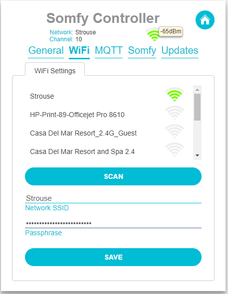
When the software is first connected it will start its own WiFi network. You will need to connect to this network to provide the WiFi credentials for your network. So open your WiFi networks and connect to the unsecured network named Somfy Controller. Once connected navigate to http://somfyserver.local and it will bring up the blank shades screen. Click on the gear icon at the upper right to open the configuration screens a select WiFi.
Select your WiFi network from the list and enter the passphrase and hit save. This will disconnect the ESP32 from its own network and connect it to your WiFi network. From here on out you can access it by navigating to http://somfyserver.local on your local WiFi network.
General Settings
Once you have connected to your local network you can now configure the rest of the software.