| data | ||
| .gitattributes | ||
| .gitignore | ||
| ConfigSettings.cpp | ||
| ConfigSettings.h | ||
| LICENSE | ||
| MQTT.cpp | ||
| MQTT.h | ||
| Network.cpp | ||
| Network.h | ||
| README.md | ||
| Sockets.cpp | ||
| Sockets.h | ||
| Somfy.cpp | ||
| Somfy.h | ||
| SomfyController.ino | ||
| SomfyController.ino.esp32.bin | ||
| SSDP.cpp | ||
| SSDP.h | ||
| Utils.cpp | ||
| Utils.h | ||
| Web.cpp | ||
| Web.h | ||
SomfyController
A controller for Somfy RTS blinds and shades
Most of my home is automated and one of the more annoying aspects are three very expensive roller shades that still don't have any type of automation attached to them. So I went searching for libraries that could automate my shades. Not only automate them but interact with them but manage their position while still allowing me to use the Telis remotes.
The research led me to several projects that looked like they would do what I want. Most of them however, could send commands using a CC1101 radio attached to an ESP32 but I really wanted to be able to capture information from any external remotes as well. In the end I did not find what I wanted so this repository was born.
This software uses a couple of hardware components. These include an ESP32 module and a CC1101 Transceiver module. The CC1101 is connected via SPI to the ESP32 and controlled using SmartRC-CC1101-Driver library.
Getting Started
Originally I bought a spring type transceiver module and could not figure out why it would not consistently receive commands from my remotes. I then went about purchasing several other transceiver modules. This led me to the conclusion that the timing algorithm I created to read the radio signal was not quite ready and any of the CC1101 transceivers work. All of them had a range over 300 feet and through a couple of walls. I finally just stopped walking.
Your first step is to connect your transceiver to your ESP32. I did this with the use of some dupont connections for now but will be coming up with a cleaner setup and project enclosure. Next you will want to install the firmware on your ESP32 and configure the radio to match your hardware connections.
Required Hardware
- 1 - ESP32 Module
- 1 - CC1101 Transceiver Module
- 8 - Dupont female/female connectors
Assembling the Hardware
You will need an ESP32 module. I used an ESP32S-WROOM-32 deevelopment board for my project. The included binary is compiled using this board. You will also need a CC1101 transceiver module. Like I explained earlier I bought several of these and they all work great. I have the blue ones with 10 pins, green ones with 8 pins, and even blue ones with 8 pins. The 10 pin versions simply have the VCC and ground pins duplicated.
The hardest part of the inital connection is determining which pins are which on the transceiver. Sadly the first module (green 8-pin) I bought only had the pins labeled with a number. As it turns out the mapping goes like this if you bought one of these boards.
| Pin | Description | ESP Pin |
|---|---|---|
| 1 | GND | GND |
| 2 | VCC | 3v3 |
| 3 | GDO0 - This is the RX Pin | GPIO 13 |
| 4 | CSN | GPIO 5 |
| 5 | SCK | GPIO 18 |
| 6 | MOSI | GPIO 23 |
| 7 | MISO | GPIO 19 |
| 8 | GDO2 - This is the TX pin | GPIO 12 |
This is how I mapped mine using the V-SPI interface of the ESP32 and two innocuous pins for RX/TX. Initially I used the onboard LED pin for RX to see when data was being sent but I think that was causing interference. If you just want this to work use the pin mapping above. The other boards are much better labeled so match up the descriptions to the pin header and you will be golden.
Installing the Software
I developed this using the painfully awful Arduino IDE v1.8. I originally installed v2.0 then found out you cannot upload the file data to it so use v1.8 and save yourself several hours of searching through forums for functions that are not supported even several years after its release. If you are using VS Code then you are on your own. The good news is that you only need this during the initial install.
First compile and upload the firmware to the ESP32. Then upload the data using the Sketch Data upload tool. You will be happy to know that once the initial install is done you don't have to go through all these hoops to update the firmware or the LittleFS file system if you are using an ESP32S-WROOM-32 module. I created a utility that is part of the software. You can install the firmware and the applicaton files remotely.
If you are unfamiliar with uploading sketches this is an opportunity to learn but be aware like all things Arduino this can be infuriating. If you are using the Arduino IDE v1.8 you will find the tool here. Sketch Data Upload Tool
Configuring the Software
From here on out everything is easy. You simply navigate the user interface to set up your controller.
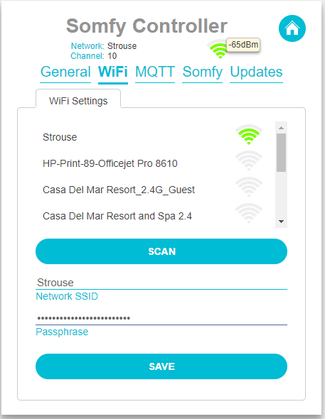
Initial WiFi Connection
When the software is first connected it will start its own WiFi network. You will need to connect to this network to provide the WiFi credentials for your network. So open your WiFi networks and connect to the unsecured network named Somfy Controller. Once connected navigate to http://somfyserver.local and it will bring up the blank shades screen. Click on the gear icon at the upper right to open the configuration screens a select WiFi.
Select your WiFi network from the list and enter the passphrase and hit save. This will disconnect the ESP32 from its own network and connect it to your WiFi network. From here on out you can access it by navigating to http://somfyserver.local on your local WiFi network.
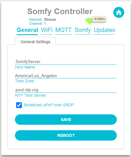
General Settings
Once you have connected to your local network you can now configure the rest of the software. The first thing you should do is set up the general tab for your controller. There are a few options here for the server. This includes the host name of your Somfy server as well as the time zone and whether the server should announce iself over Universal Plug & Play. If you have isolated the device on your network you can choos a timeserver that is local to your network. This will ensure time logs are in sync.
Somfy Transceiver Settings
There are two parts of your shade setup that need to be configured. The first is to set up the transceiver so that it can speak with your somfy remotes and shades. You will find the transceiver settings under the configuration (gears menu) on the Somfy Tab. You should only need to configure the transceiver once but it is important that the settings are correct.
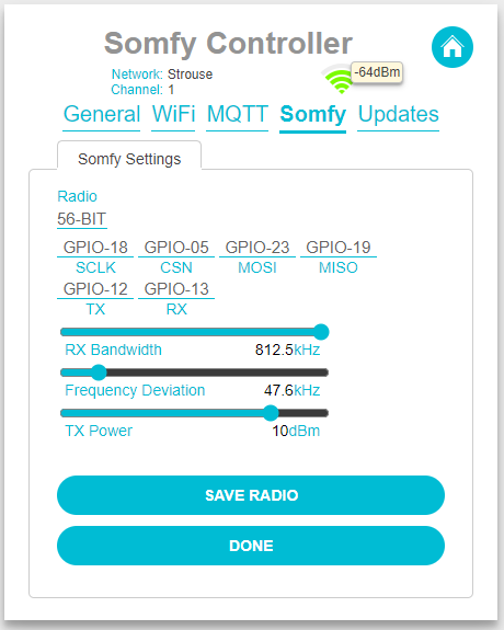
First select the radio type. This software supports either the 56-BIT Somfy remotes or the 80-BIT Somfy remotes. It will not support both at the same time. Maybe at some point I will figure out a way to support both protocols at the same time but for now spen another 10 bucks and build another device if you need both. If you do not know which radio type you have select 56-BIT for now. If we cannot hear your existing remotes in a later step you can come back and change it.
While you were hooking up your hardware above you selected the ESP32 gpio pins that are to be used for the transceiver. You simply need to match these with the pins you selected. It will default to the configuration outlined above.
There are some radio configuration options supplied as well. These determine how well the software can hear your remotes and how loud it will speak when talking to your motors. The RX Bandwidth and Frequency Deviation focus on the receiving side of the transceiver. RX Bandwidth refers to how big the transceiver's ear is and the Frequency Deviation refers to how much noise it can filter out. Unless you are having issues with competing signals or you want to reduce the range then leave these at 812.5kHz and 47.6kHz respectively. If you are a radio head and not just somebody who has listened to the band on occasion then these settings sould be familiar. The base frequency for the radio is already tuned to 433.42mHz carrier frequency.
The TX Power determines how loud the transceiver shouts at the motors. You can leave this at 12dBm unless your transceiver is one of the ones that only support 10dBm. Either way this range is much further than the typical somfy remote.
Once you are satisfied with your settings press the Save Radio button then press done. We can now set up our shades.
Somfy Shades
To add a shade click the Add Shade button on the Somfy Tab under the configuration menu. This will bring up a screen that allows you to set the configuration for the shade. The software supports up to 32 shades each with up to 5 linked remotes. If you need more than that you can modify the SOMFY_MAX_SHADES and/or the SOMFY_MAX_LINKED_REMOTES defines in the Somfy.h file or stop being so cheap and spend another 10 bucks for a second server.
At this point it is probably beneficial to provide a little bit of a glossary.
- Shade - The physical Somfy motor that drives the covering.
- Remote - A physical device such as a Telis channel that is used to control the said motor.
- Linked Remote - A remote that is used to control a particular shade and the Somfy Server knows about. The server needs to know about these so that if a button is pressed on an external remote it knows what the current position is of the shade.
- Pairing - The process of linking the defined shade in this software so it can control the shade.
You must provide up to 20 characters for the name of the shade. The Remote Address is expected to be unique for all known addresses and is generated from the MAC address of your ESP32. This can be any value so long as it is unique. Change it at will but did I mention that it must be unique and the algortithm to calculate a new address only makes sure the address is unique among all the addresses that the Somfy Server already knows about.
The Up Time and Down Time fields are the number of milliseconds it takes for the shade to travel from the down position to the up position and vice versa. This value is provided in milliseconds so if you are counting the number of seconds it takes 10 seconds = 10000 milliseconds. So if it takes 9.5 seconds to go from full down to full up then that would be 9500 milliseconds. Keep in mind the up time and the down time can be different depending on the weight of the fabric and you can make adjustments these values at any time in the future.
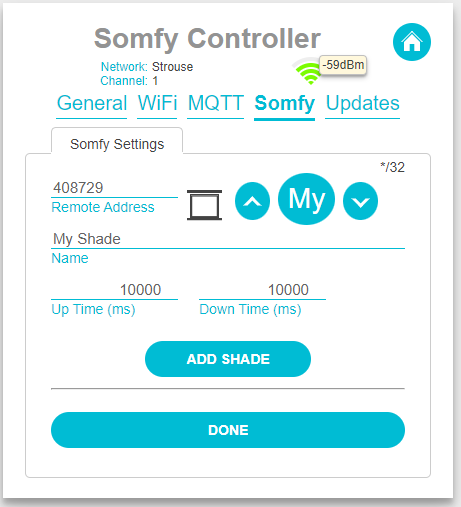
Once you are satisfied with your settings press the Add Shade button. This will change the screen to include more button functions.
- Save Shade - Saves the current settings for the shade
- Pair Shade - Allows you to pair the shade with the somfy motor
- Link Remote - Links the channel on your Somfy remote to the shade. This ensures the position of the shade can be known at all times. You can link up to 5 channels to each shade. Beyond that you probably need to simplify your life because you have remotes strewn everywhere. Honestly you should get checked.
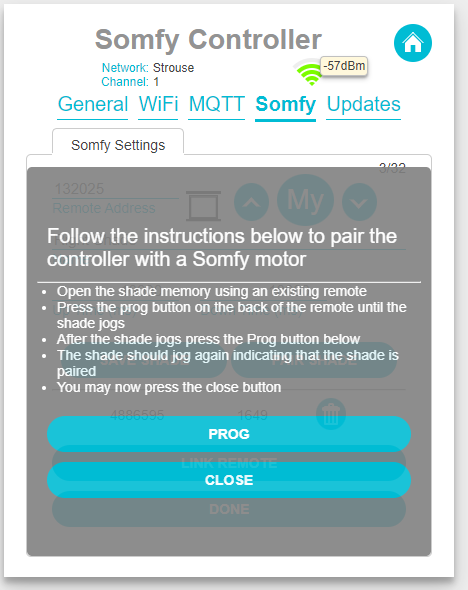
Pairing Your Shade
In order to control your shade motor you will first need to pair it with the motor. To do this navigate to the shade editor under the config menus by clicking on the Somfy tab. A listing of all the shades you have defined will be listed on this tab. On left side of the shade in the list there will be an edit pencil. You guessed it you should click on it to bring up the shade editor window. If you just added the shade and pressed the Add Shade button you should already be here.
Click the Pair Shade button to bring up the pairing screen. This will contain instructions on how to put the motor into pairing mode so you can proceed. After the motor jogs press the Prog button and the motor should once again jog to tell you it was successful. There is no communication from the motor to the remotes so I am relying on you to verify that the motor jogged after pressing the Prog button. If it didn't then don't say it did. You will have to go through the unpairing process if you aren't honest about it.
The pairing and unpairing process is essentially the same but in either instance Somfy does not provide any digital reponse that the pairing was successful. The only response is a visual one from the shade when it jogs. So it the shade does not jog after sending the response simply perform the unpair process without putting the shade into paring mode and try again. If you followed the procedure correctly this will just work. The range for the Somfy Controller is reallly really far and over the hill and through the dell.
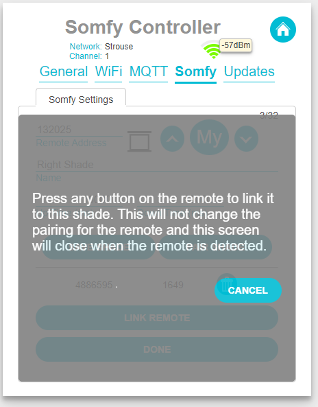
Linking Remotes
Once you have paired the shades it is time to link the other remotes you use to open and close the shades. This linking process makes sure we capture every movement of the shade so that its position is always accurately reported. Now that you have been through the pairing process and saw how painless that was, click the Link Remote button to bring up the linking window.
When this screen is open the controller is listening for any remote out there that is sending a command to the shade. Simply press any button on the remote you want to link. If you are having trouble deciding which button to press, press the up button. Once the remote is detected it will automatically close the link remote window.
Next Steps
While the interface that comes with the Somfy Controller is a huge improvement, the whole idea of this project is to make the shades controllable from everywhere that I want to control them. So for that I created a couple of interfaces that you can use to bolt on your own automation.
My first order of business is to create a Home Assistant integration using the underlying socket layer. Yep it has sockets too. I will get around to documenting these as time permits. There is also a Rest interface built into the software for controlling the shades. This is also used by the UI to configure the shades but the most interesting command is the sendShadeCommand endpoint.
This can be executed as a GET, POST, or PUT command. The command can be any one of the following values.
- U, UP, or up
- D, DOWN, or down
- P, Prog, or prog
- M, My, or my
- My+Up, or mu
- My+Down or md
- Up+Down or ud
For any of the commands you can put the arguments on the command line as follows.
To send the shade in any direction:
/sendShadeCommand?shadeId?command=up
To set the shade percentage to 35% closed:
/sendShadeCommand?shadeId?target=35
MQTT
There is also an MQTT command and reporting interface. To enable your broker connect it in the configuration pages under MQTT. This will begin reporting the shade status to your broker under the topic you assigned.

To move the shade up, down, or stop set the /{shadeId}/directon/set topic to -1 for up 0 for stop or 1 for down. This will begin moving the shade in the specified direction or stop the shade if you set it to 0. To move the shade to a position simply set the topic /{shadeId}/target/set to the percentage closed that you would like.
Now that this part of the controller is complete, I will be creating an integration to Home Assistant.